Lopolight Control Hub 500-001
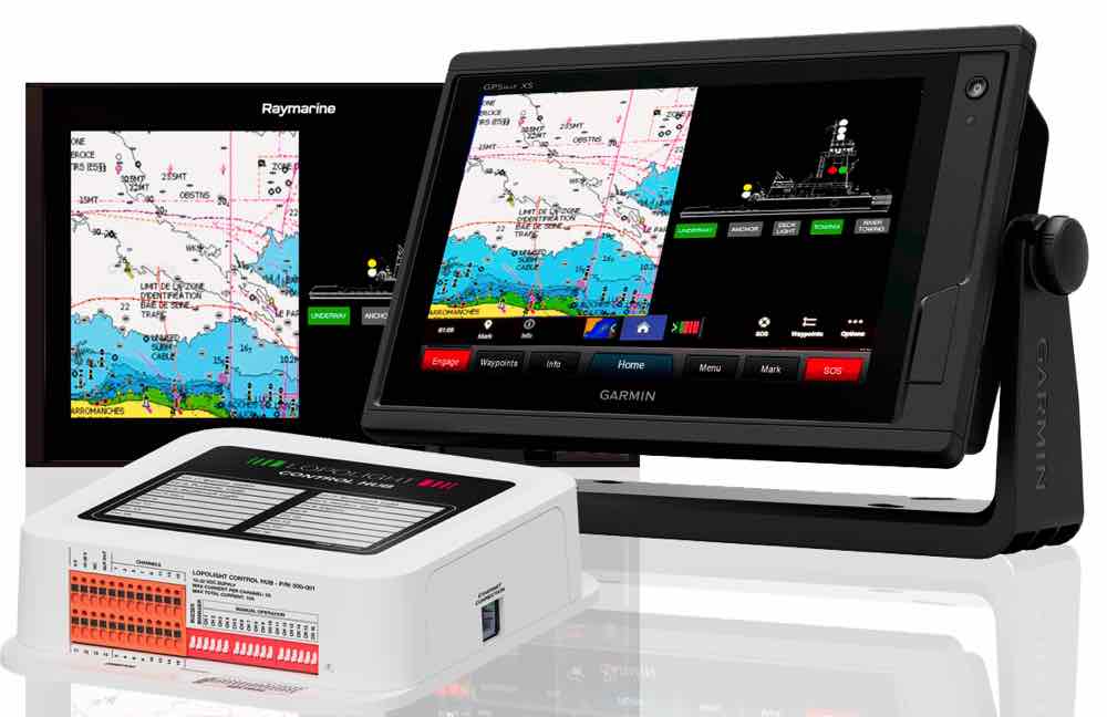
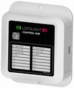
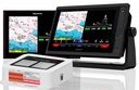
The Lopolight Control Hub is a 16-channel control and monitoring unit for navigation lights, deck lights and other onboard equipment. It connects to your MFD over Ethernet and appears as an app, which shows a plan view of your vessel with each light drawn in its correct sector. From there, every light can be switched, grouped and monitored from the helm.
The hub is designed around Lopolight navigation lights, but it also controls other brands of LED lights and auxiliary equipment. That makes it a practical retrofit for both sailing yachts and motorboats.
One-touch light configurations
Individual channels can be combined into groups. Each group is an on-screen button that sets any combination of lights with one press.
- Create as many groups as you need, for example Sailing, Motoring and At anchor
- Set each channel in a group to switch on, switch off or stay unchanged, so lights such as not-under-command can carry across states
- Groups can switch each other off, so selecting Motoring cancels Sailing
- Four hardware inputs let you run any group from a physical pushbutton, even with the MFD off
Light monitoring and automatic switchover
The Control Hub measures the current each channel draws. If a light fails, it raises an audible and on-screen alarm, even with the MFD switched off.
- Lopolight lights: start-up self-test and lifetime monitoring
- Other LED lights: current monitoring, with an alarm if the draw falls below 20 mA
- Primary and spare pairs: automatic switchover to the spare if the primary fails
Compatible displays
The Control Hub connects to the MFD network over Ethernet (RJ45), not NMEA 2000 or SeaTalkNG. It appears as an app on these displays:
MFD brand | Supported range | Ethernet cable required (not supplied) |
|---|
Garmin | GPSMAP series with latest software, via OneHelm | Garmin Marine Network cable, or Cat5 with Garmin connector kit |
Raymarine | Axiom series, LightHouse 4 version LH4.7.172 or newer | Raynet to RJ45 cable |
Furuno | TZtouchXL series with latest software | TZtouchXL LAN cable (WP RJ45 to non-WP RJ45) |
Simrad / B&G | Touch-control MFDs [MODELS TBC] | [TBC] |
A built-in web server also lets you set up the hub from a laptop or tablet browser.
Compatible lights and equipment
The 16 outputs drive Lopolight navigation lights and other brands of LED navigation lights. They also run deck, boom, cockpit and docking lights, wipers and fans. Loads above 2 A can be switched through a relay, and channels 1 and 14 support PWM dimming from an on-screen slider.
Built-in fail-safes
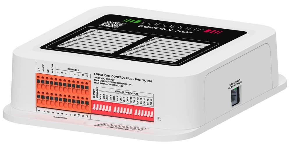
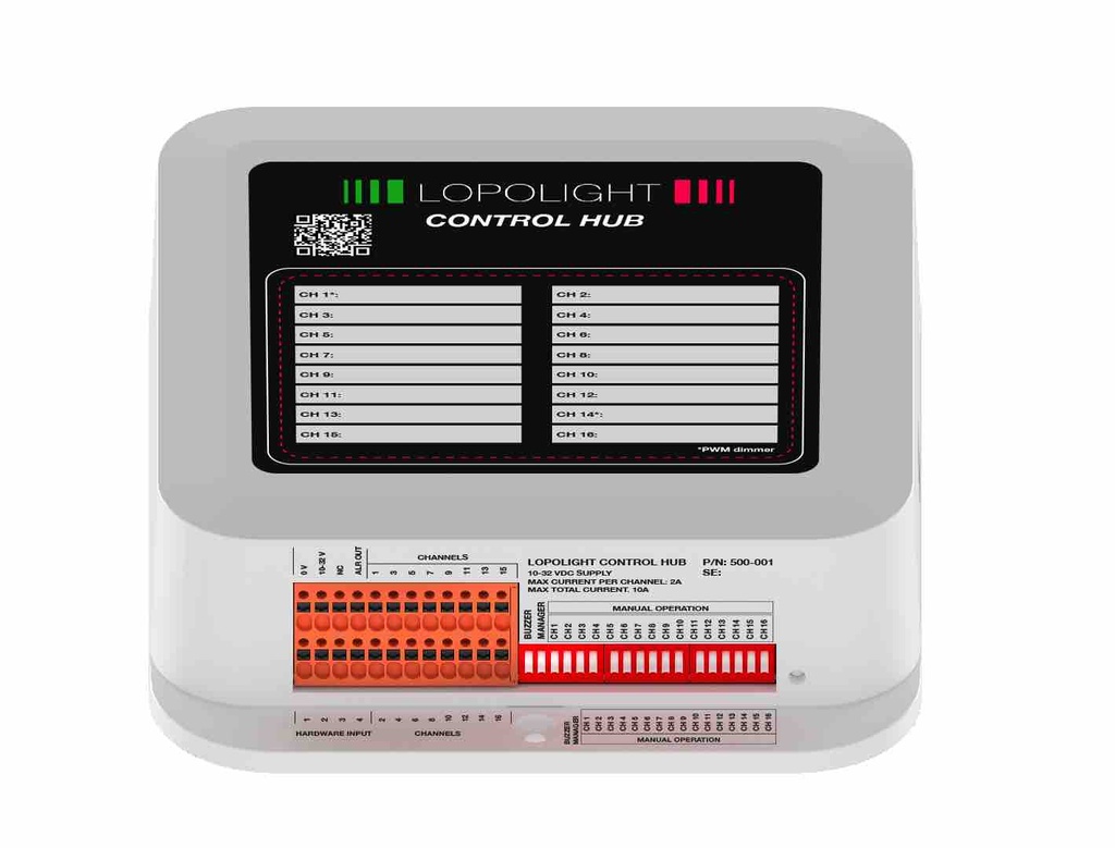
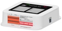
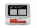
- Manual override: each channel has its own DIP switch on the hub. It turns that output on even if the MFD, the network or the hub's processor fails.
- Protected settings: a dedicated DIP switch hides the settings menu, so crew can't change the setup by accident.
Technical specifications
Specification | Value |
|---|
Dimensions | Approx. 150 × 150 × 40 mm |
Supply voltage | 12 or 24 V DC nominal (10–32 V DC) [CONFIRM: product page states 9–32 V] |
Factory setting | 24 V (12 V systems must be reconfigured at setup) |
Outputs | 16 monitored or unmonitored channels |
Max load per channel | 2 A |
Max total load | 10 A |
PWM dimming | Channels 1 and 14, 200 Hz, up to 2 A |
Monitoring threshold (non-Lopolight lights) | Alarm below 20 mA |
Hardware inputs | 4, opto-isolated, 10–32 V DC activation |
External alarm output | 3.3 V DC, high-going, 200 mA max |
Network connection | Ethernet, RJ45, IP address via DHCP |
Manual override | 16 DIP switches, one per channel |
Recommended main protection | 10 A slow-blow fuse or C-curve breaker |
Compass safe distance | 1 m (3 ft) |
Warranty | 2 years |
What's in the box
- Lopolight Control Hub (500-001)
- Quick guide
- Wiring schematic diagram
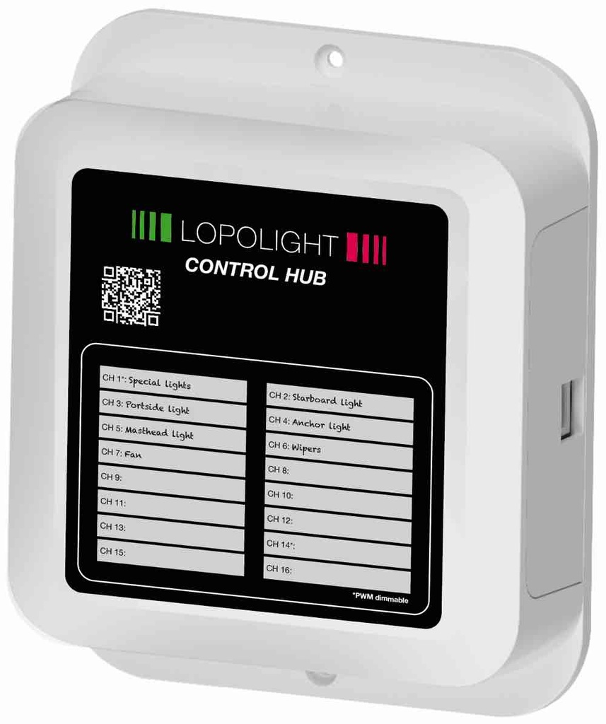
- Connection layout sticker, for recording what's on each channel
The Ethernet and power cables aren't included. See Compatible displays for the cable your MFD needs.
Installation
Lopolight specifies installation by a skilled marine electrician. Mount the hub somewhere dry and ventilated, at least 1 m from the compass, and keep it accessible so the manual override switches can be reached. Full wiring guidance is in the installation manual.



 and then Add to Home Screen.
